Monday, October 27, 2014

Post #12: Success (and Failure) and COOL

Meet Rue, my new time sink! :)
Sorry it took so long to create post #12, but recently had a new addition to the family, and sleep, well, sleep is overrated :).  Meet Rue, the competition for my robot building time and of course, my sleepy time :).

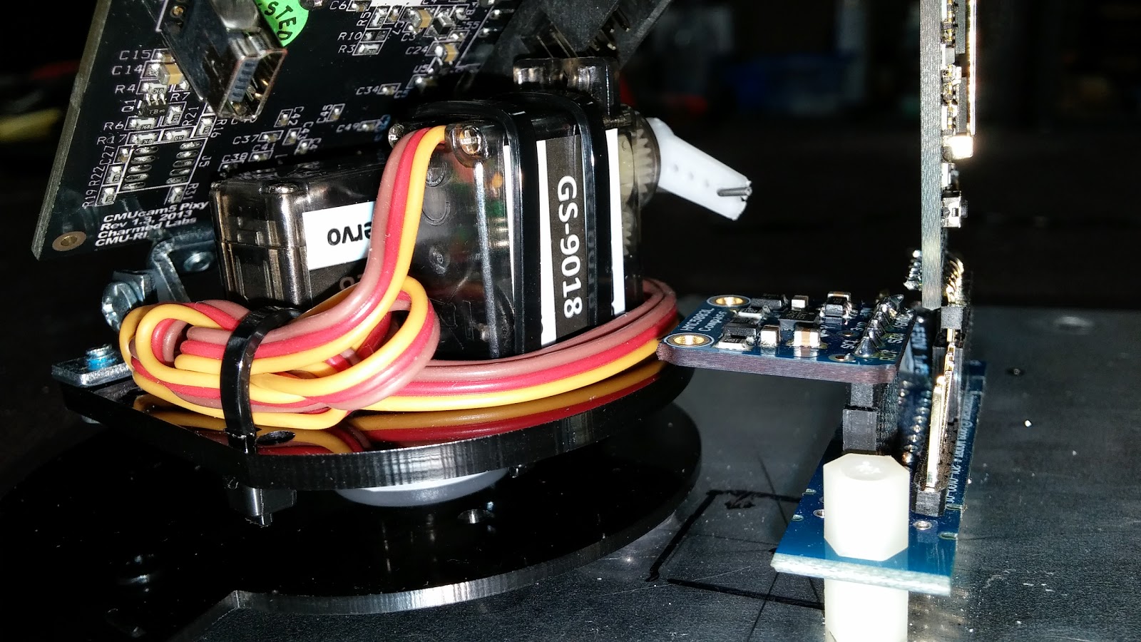
Also, I was waiting on more pins from Jameco so that I could make more wires, they came in on Saturday.

First the SUCCESS!

The new bluetooth module from Adafruit came in, remember when I said the first one wasn't working and I posted a link over to the support?  When I escalated to the support email, they responded quickly and offered to ship me a new one at whatever shipping speed I wanted, that was super cool, but I chose the cheapest shipping route anyway.  The new bluetooth module rocks, I was able to hook up my old Thunderbolt and my new LG G3!  I was even able to write some code down in the Arduino and read out the control characters sent.  It works great.  

With the exception of 2 or 3 wires left to hook the PIXY up to the Arduino, I'm for all practical purposes WIRING COMPLETE as well!  This is quite a milestone, this means that I can now focus on the code. I've been able to import the SHARP IR sensor libraries, I found a library for motor controls that I'm going to convert to regular code (it uses Delays, very bad for simultaneous control of anything), and even have all the pins defined and set up in the "SETUP" section of the code.  When I get it more complete, I'll post another page with the version 1.1 code (version 1.1 should have motor controls, bluetooth reads and IR sensor reads, along with the compass reads already done).

Now the FAIL :(

EVEN after checking the wiring on the SHARP modules 4 times (yeah, both of them), printing out the datasheets and triple checking my hookups, I put 5V on the Analog Output pin (yeah, on both of them!), thus huffing my IR Proximity Sensors (did I mention, BOTH OF THEM?)! OY VEY!  As I was writing code, I kept smelling something cooking, and it didn't come from the kitchen.  I smelled all around the bot, couldn't find it, then touched one of the sensors and it was burning hot!  ugh.  So ordered 2 more from Amazon, they will be here Wednesday.  Luckily, it will be an easy swap, but.... argh.  I guess this one we can blame on Rue and no sleep!  Oh well.  Can't make an omelet without breaking some eggs.

AND THE COOL

Another shot of the Arena, all set up!
The club is getting better and better at setting up the Arena. This pic shows it set up with all the blocks in place.  The thing is the size of a small bedroom!  It is very cool.  Now it is time to test the bots, make adjustments, troubleshoot failures (these can be a real shot in the dark).  The teams have done a great job to get to this point... but they are only in prototype stage, time to make improvements! I can actually help here as well, so now I don't feel so helpless!  I can least help assemble and tear down the arena LOL. 

MORE COOL!

Remember a couple posts ago I promised to post the video of the PIXY mounted and running on the creeper?  Enjoy.


Thursday, October 16, 2014

Post #11: Wrangling with Wiring

5 hours of wire wrangling
Sweet!  My parts (pins, wire, heat shrink tubing) came in!  So I removed all my old wiring I really didn't like, started making custom cables to the lengths that I really like WAY BETTER.

Took the whole top layer off, rewired the feeder wires (motor controls, power converter).

My special connector for the PIXY came in, took it back apart, assembled the special connector and re-assembled!  So far, I'm very pleased with the results!  (Even retested the PIXY, I'll post a new video when if finally uploads!)

Finally!  I can now hit the main power switch on the side of the creeper and have my Arduino power up and start running!  The program (from post 10) is still installed, so if the compass is hooked up correctly, the watchdog led on the Arduino should flash every time the compass is read. It does!  I'm so pleased.


30 year old Crimpers
Anyway, to create my custom cables, I used an old pin crimping tool I used 25 years ago when I installed process control equipment in paper mills.
using the Zippo to shrink the wrap
These pics show the crimper, the pins and the heat shrink tubing I protect the pin with. A standard Zippo is all I used to shrink the wrap.


Felt good to get those old crimpers back out... ah good times. Pretty sure they don't make them like that anymore.


TIME OUT

Lets take a quick look at the progress our bright young engineers are making on their competition bots.  Today we assembled the competition arena and the students even got to run their bots around and practice a bit.  One team is rebuilding, they really didn't like how their bot was operating with the angled omni wheels.... But the other two are ready, practicing and looking for improvements.  Enjoy!
The Freshman team's bot
The Senior teams bot

The arena, before the floor was placed.  It is pretty large, 12' by 12'

 TIME IN

Back to the creeper.  Adafruit is sending me a new Bluetooth (their Bluefruit module).  I tried everything I could think of, multiple times.... and just could not get the device to present a Serial profile for me to connect to. Adafruit support agreed and are sending me a new one free of charge. That is pretty good support. Feel free to read the thread HERE.  I went back and forth a tiny bit, but in the end, that first Bluefruit just wasn't cutting the mustard.  Hopefully, in the next post I'll have more software ready.

One of my upcoming challenges is figuring out the knobs I need to turn for motor controls.  I plan to use (at least right now) one PID controller object to control the turning of the bot.  For turning, the setpoint is going to be heading (compass vs pixy object location).  This will probably end up being complex, but it will all be explained in the end.

Thanks for reading.  We'll have some more fun stuff soon, I promise!  (wiring is not fun).


Sunday, October 12, 2014

Post #10: Some Progress, Some not so much

I've made a good step forward, and like with all engineering projects, a step back.  First the good.

The Good (wiring)

I think I have the wiring situation figured out.  I ordered some parts from Jameco: 6 different colors of 22AWG stranded hookup wire, some female pins to crimp on the end and while I was there, I found the specified power connector for the PIXY, a 2 pin female MOLEX connector so that I can power the PIXY separately instead of drawing current out of the Arduino.  I'm thinking this is going to be better as the PIXY seems to want to draw some current driving those servo's around.

The Good (first Arduino Sketch)

Output of Compass Module
I have written my first Arduino sketch (See it here).  I hooked up the compass module, started with the adafruit base and sensor libraries, and it went together pretty smoothly. Once the basic sketch was working, I began modifying it to remove all the bad things you don't want to have running in a real production Arduino script, like "delay" functions.  I replaced all the delay functions with a Timer function so that the loop can keep running, we just won't hit the compass every time through the loop. The picture on the right here shows the Arduino sketch running and reading from the compass the current heading information and converting that into Degrees!  That was an easy peasy thing to do, giving me hope the rest of the project is going to be this easy! :)

The Bad (Bluetooth not so easy)

The simplest hookup possible
Well, of course, I should have expected it.  No engineering project is ever easy, if it was, they wouldn't need engineers I suppose. I wired up the Bluetooth module and it seemed to work.  I was able to pair up my windows pc and my android phone, so far so good!  NOT SO FAST. The Serial protocol won't stand up properly. After several hours of messing around with it using both my Android phone and my Windows 8 laptop, nothing seems to be able to get the Serial protocol to start. So I opened a help ticket with the good folks at Adafruit.com (where I bought it).  If you click on that link you should be able to see the support request and the pictures I included to help them help me.

Hopefully Adafruit can tell me what I'm doing wrong and I can move forward! :). If not, when I get my wiring parts I'll hook up the IR proximity sensors.  I found some libraries that help stabilize the readings from them and make them more useful.  More on that in the next post!

Thanks for reading.


Tuesday, October 7, 2014

Post #9: Construction Complete!

The Creeper!
The long awaited (at least by me) completion day has finally arrived! At least the physical/component construction phase at any rate.

BEHOLD!  The Creeper!

Over the last 8 posts, I pretty much changed my mind several painful times, and no difference in this post.  But that can wait.  Did I mention....

BEHOLD!  The Creeper!

You can't imagine how relieved I am to finally reach this stage.  I started to wire things up a bit but am extremely unhappy with the prefab wiring I purchased, they are either too short or too long and the connections are too weak.  You can see all the wiring hanging out the sides, oh well, a challenge for another day.  Right now I'm thinking i'm going to Google around a bit to figure out how to make my own cables.

click to see larger version
Anyway, as I hinted earlier, I changed my mind quite a few times down this road, and since my last post, yet again.  As I was locating parts and drill holes, I noticed that the compass module, located where I wanted it (top dead center, remember?) would place it very close to the servo's on the PIXY.  This had me a bit concerned, so I paused and googled about that compass module we have, and it turns out I was right.  It is sensitive to servos and motors and everyone recommends to locate it as far away as possible from both.  I still have the bluetooth located next to it, this may cause a problem down the road, but that is yet another bridge for another day.

the Pixy pan/tilt base plate
So, back to the drawing board.  I decided to remove the compass and set it aside for now.  I have a new anchor item, the PIXY has to go on first.  Lets figure out how to mount it and then worry about the compass.

PIXY pan/tilt base mounted
In order to mount the PIXY, you first have to disconnect the base plate and locate it. Mark your mouting holes, drill, tap.  Now, when you screw down the plate, it is made of plastic, so I was afraid I was going to break it if I made the screws too tight.  I luckily bought some nylon washers earlier at Home Depot, they were almost the perfect thickness.  I put a bit of loctite on the threads, screwed it down snug... the PIXY will remain secure.

for mounting PIXY to servo plate
The PIXY attaches to the servo plate that mounts on the base plate, this is done from the bottom, so I drilled a hole big enough to be able to get that tiny screw back in the servo plate that the PIXY mounts to.

Thats done. Now lets worry about out compass.
Bluetooth and compass at back of robot

I think the farthest point away from everything, the drive motors, the Arduino, power conditioning circuit, motor controller, etc.... would be on the very back of the bot.  Mounting it 180 degrees out of phase would take it even farther away from everything, no biggy, we will deal with phase correction in software.  This picture shows them mounted on the back, 180 degrees out of phase.


Next up, WIRING.  Lessons on making your own custom connectors coming to a blog near you....

Then.... testing out the component parts.  First the IR Distance sensors, then the compass, then the bluetooth, the compass -and- the bluetooth, THEN the PIXY (hardest for last).

Until then, I'll leave you with one more shot of THE CREEPER!

The Creeper.


Friday, October 3, 2014

Post #8: Fumble Recovery

Fumble Recovery
Tonight was a good night, I recovered my own fumble.  In the last post I mentioned how I created a circuit that was one giant short circuit, remember? After searching for a plan B, it occurred to me that if I had just a tiny bit of luck (actually, 50/50) and I have access to the traces on my little perfect board, I could cut them away and recover my mistake! Yay! As luck would have it, I can cut away the traces and get back to my perfect mounting scheme! (for all you experienced robot makers, this is probably old hat for you...).  I took a hack saw blade and ran it across the back in between each of the pins. Doesn't look nice, but you won't see it anyway.  It worked! An ohmmeter proves that no pin has continuity to any other pin it isn't supposed to! Plan A back on track.

Compass, top dead center.
Compass with Bluetooth
In fact, I finished soldering on the pins to my bluetooth and compass circuits, mounted this pcb to the top shelf and installed it all up just so I can 1) see if my compass is top dead center and 2) mark mounting locations for the rest of the boards. As you can see, the compass is top dead center (not sure if you can see the pencil lines that crisscross over the center of the panel). Next to the compass is the Bluetooth, there was enough room on that board for both. Mounting it off center gives me the space I needed to center the compass.

I've marked my holes for the Arduino and a power bus, now would be a good time to assemble the PIXY and see what it is going to look like so I can figure out how to mount it. The little black dots you see on the left of the mounted circuit mark the holes for the Arduino (I have to take my creation off the board before I drill new holes). That leaves the space over on the right (front) of the panel for the PIXY. The base on this thing is kind of big, I'm going to think about it for a bit, good ideas always come to me overnight.

the Assembled PIXY!
So, lets get to know our little PIXY. Here is a pic of the PIXY next to the platform. It is pretty large compared to the space I have to mount it. There are 4 holes on the bottom plate that look like I'll be able to use for mounting, but the challenge, how to re-attach the servo plate.... I'll think on this a while.

I followed all the instructions on the cmucam.org wiki page, sometimes twice.... can be confusing at times, I assembled a couple of things backwards, twice :).  Anyway, once it is all assembled and the wires all tucked away nicely, I went ahead and ran the pan/tilt demo. I'm glad I did, the pc kept complaining that it was using too much power, so... that means I'll really want to think about powering this little guy. Anyway, check out the pan/tilt demo, pretty much ran out of the box. I picked the yellow handles on my electricians tool to track, did pretty well!

Not bad for straight out of the box. There are tuning parameters for the proportional and derivative gains on the tilt and pan servos, but I didn't mess with them. The Arduino will be controlling the servos ultimately (telling the PIXY where to move the servos) so tuning the PID controllers in the Arduino will be the place where that gets done.

Anyway, good night.  Time for sleep :)